More is less
Lenses have played an important role in people’s lives since long before the 17th century, when the Laterna magica or magic lantern was developed [1]. The first optical products made by humans are considerably older. In early times, they were made by grinding or polishing
mostly quartz to produce the desired properties.
Today, it is hard to imagine everyday life without lenses. Glasses, cameras and projectors are obvious examples, but me- trology and automotive engineering are other areas in which they play a major role. A corollary of this wide range of ap- plications is that the mechanical manufacture of lenses is constantly being presented with new challenges, and so not only the manufacturing process but also the underlying material, quartz, is in need of alternatives.
Back in 1933, Röhm & Haas AG launched a polymethyl methacrylate (PMMA) under the brand name Plexiglas [2]. A good seven years later, in 1940, Heinrich Wöhlk developed a product whose forerunner had first been proposed by René Descartes back in 1636 [3] – the contact lens [4]. A whole series of developments followed, but the example of the contact lens illustrates for how long and to what extent lenses have fascinated mankind.
A decisive, portentous step was ultimately taken when plastics started to be used in the manufacture of products that possess optical properties. Injection molding, the process by means of which the two components – plastic and lenses – are combined, is capable of producing large volumes with reproducible results. However, it also has to contend with technical hurdles such as uneven shrink- age, stresses and sink marks.
Since the requirements imposed on products with optical properties are much higher than those on technical products [5], a further manufacturing process that merits consideration is injection compression molding. Combining injection molding and compression molding affords a way of optimizing both process- related (e. g. filling pressure) and component-related properties [6]. The main focus here is on homogenizing both material and component properties.
Injection compression molding delivers superior component quality compared to injection molding but can incur considerable costs. This is where process simulation steps in. Not only can each process be modeled in the same way as for technical components, but optical proper- ties such as birefringence, refractive index, fringed pattern, and retardation can also be simulated. Thus, simulation is a tool that optimizes the production of optical parts and also provides criteria for a well- informed decision as to which process is best suited to which product from a qualitative and an economic point of view.
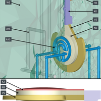
Fig. 1. Two-layer injection molding: visualiz- ation of the simulation model for the first and second component, including mold and temperature control.
Simulation Insights and Differences
Process simulation is a long-established tool for garnering knowledge about genuine errors – and not just the kind suggested in the context of trouble- shooting. It is also used in product devel- opment to identify and, if possible, rule out potential problems from the outset. Furthermore, simulation can be used to evaluate alternative processes and ma- terials. However, in many cases, process simulation is just one part of the development chain, and that is why the coupling together of different simulation methods is growing in popularity. For instance, in many companies it is standard practice to couple process simulation with structural simulation as a way of transferring addi- tional data such as anisotropic material properties, weld lines, etc.
Such coupling methods are also available when it comes to designing lens products. For example, the refrac- tive index or even the deformation can be exported from Moldex3D to Code V, a software for optical design. This approach yields more meaningful results,
e.g. in terms of possible imaging errors, and lends itself to both injection molding and injection compression molding.
It must be pointed out that the simulations for both injection-compression molding and optical properties differ noticeably in some aspects from the routines actually employed in injection molding, namely process control and treatment of the simulation model. The simulation is performed in 3D and, for both processes, is broken down into the various phases of filling, compression, packing, and cooling.
Thus, not only can properties such as birefringence and residual stresses be simulated, but a distinction can also be made between thermally induced and flow-induced properties.
A special situation arises in connection with compression. In order that the compression stroke may be simulated, the mesh is deformed as a function of time. Consequently, the domain changes during the course of the simulation. Plastics are often described by parameters such as viscosity, pvT behavior, thermal conductivity and specific heat capacity, coefficient of linear thermal xpansion (CLTE), Poisson’s ratio and Young’s modulus. In order that the specific results concerning the optical properties may additionally be obtained for both processes, a knowledge of the viscoelastic properties of the plastic is needed.
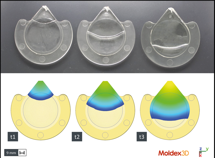
Fig. 2. The filling study shows the high level of agreement between injec- tion molding reality and simulation
Multi-Layer Injection Molding Shortens Cycle Time
Plastic optical parts that serve as attach- ment lenses for defined light distribution, for example, can have wall thicknesses of up to 60 mm. In traditional injection mold- ing, the quality of the lenses is assured by having cycle times lasting in some cases more than 20 min. The need to address this and thus enable series production in- spired the development of multi-layer in- jection molding for thick-walled lenses. Multi-layer injection molding is similar to multi-component injection molding and consists in producing the finished lens over a number of molding processes, thereby shortening the cycle time to an economically acceptable level.
Both core-back technology and transfer and turntable technology, which are already established concepts for manufacturing multi-component parts, can be used in multi-layer injection molding. Furthermore, more uniform cooling and thus lower levels of residual stress can be obtained by using a conformal temperature control system and/or adopting a dynamic temperature control strategy. The production of optical lenses in multi-layer injection molding by the core-back technique, and its simulation, are explained below.
Simulation Model and Simulation Sequence for a Biconvex Lens
The geometry employed [7] was sup- plied by the Institute for Plastics Pro- cessing (IKV) at RWTH Aachen University, Germany. A two-layer, aspherical, biconvex lens was simulated. The over- all view of the simulation model (Fig. 1) shows the mold (WZ), the general cool- ing system (aKS), the conformal cooling system (kKS), the hot runner (HK) and the cold runner (KK). Shown below this are the pre-molded part (VS) and post- molded part (NS) and the compression zone (KZ) for the injection-compression molding process. There is no compres- sion zone in the injection molding pro-cess.
The chosen material was PMMA (type: Plexiglas 7N; manufacturer: Evonik Performance Materials GmbH, Darm- stadt, Germany). The shape geometry was created with the aid of a mold incor- porating core-back technology [8]. This mold design makes it possible to produce pre-molded and post-molded parts in the same cavity by means of a hydraulic core-retraction system. The compression stroke of the compression zone is executed via a compression frame construction and the clamping movement of the injection molding ma- chine.
In the injection molding simulation, the first shot fills the cavity of the pre- molded part. If this meets the predetermined demolding criteria, the physical condition of the part is transferred for the second shot. The mold core on the clamping side is retracted to expose the cavity of the post-molded part. Then, in the second shot, the post-molded part is given its shape. In the injection compression molding simulation, the pre-molded part is created and transferred in the same way as in the injection molding. When the post-molded part is being filled, the compression core closes under a defined compression force and speed profile as soon as a pre-determined filling volume has been reached.
The IKV conducted a filling study for the post-molded part made by injection molding, so that it could be compared with a simulation performed by SimpaTec. The three selected time steps (t1 – t3) clearly show the good agreement be- tween the simulated flow front and the real flow front (
Fig. 2).
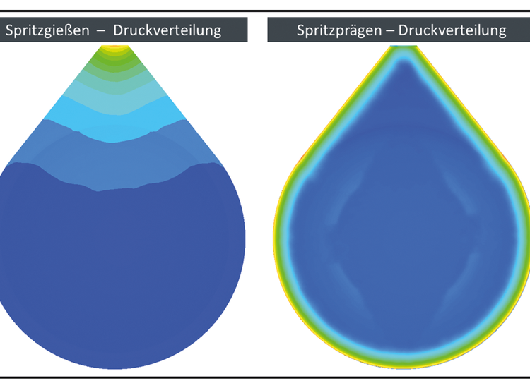
Fig. 3. The pronounced pressure gradient that occurs during injection molding (left) contrasts with the homogeneous pressure distribution arising in injection-compression molding (right).
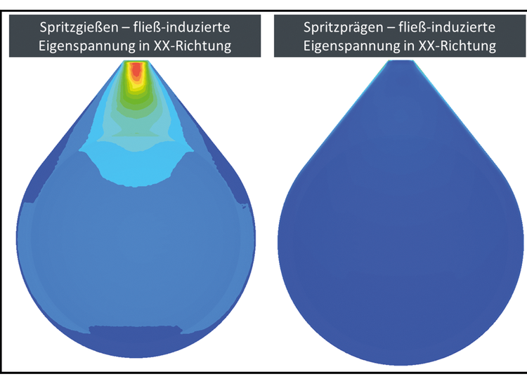
Fig. 4. Flow-induced residual stress in the XX direction is more pronounced in injection molding (left) than in injection-compression molding (right).
Comparison of Simulation Results
The results of the injection molding and injection-compression molding simu- lations were compared. The pressure dis- tribution at the end of the packing phase (injection molding simulation) and after the compression phase (injection-com- pression molding simulation) shows a pronounced pressure gradient starting from the gate location in the case of injection molding. In contrast, the pressure distribution on the optical functional sur- faces of the lens made in the injection compression molding simulation is more homogeneous (Fig. 3).
When the local flow-induced residual stresses in the XX direction are displayed as false-color diagrams, clear differences
also emerge at this point between the simulated lenses made by both types of simulation, as was the case for the press- ure results (Fig. 4). In contrast to the injection molded lens, the injection compression molded lens is characterized by a lower residual stress gradient, resulting in better optical properties.
There are clear differences in the flow- induced and thermally induced fringed patterns of the simulated lens; both effects may also be superposed (Fig. 5).The simulation results can be used to conduct defect analysis as part of a quality assur- ance regime, with the aid of real polarized images. The separation of the flow and thermally induced fringed patterns can also be used for targeted root cause analysis.
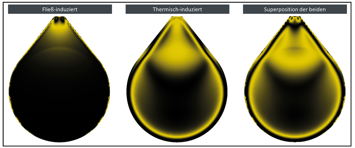
Fig. 5. Flow-induced and thermally induced fringed patterns and the superposition of both effects for the simulated lens using injection molding as an example.
Conclusion
Injection molding or injection compression molding? Conformal versus conventional cooling layout? These are just two out of a whole range of questions that can be answered in advance by conducting a simulation. There is no question that traditional injection molding simulation provides many answers. However, the coupling methods de- scribed above show that the possibilities are now much greater, yielding in advance an enhanced product under process conditions which have been opti- mized from both technical and economic aspects.
Thanks:
The authors thank Dr. Malte Röbig for the information provided.
Englisch Version was first pusblished in Kunststoffe International 04/2020.


